1.5 | Setting up a Pixotope machine
Video tutorial - Director walkthrough - SETUP (Pixotope 1.1).
Planning a multi-camera or multi-machine production?
Learn more about 1.5 | Single- and multi-machine setups.
Starting Director
- If this is the first time you have started the Director, please refer to Start Director
- Log in using a Live license
- Check to make sure you are in SETUP view (you can see from the drop-down in the top left-hand corner)
Learn more about the different views in Director: 1.5 | Adjusting levels from Director.
Creating a project
- Click "Create a new project"
- Name your project
- Only alphanumeric characters are allowed, and it is recommended that the name be no longer than 20 characters (Unreal Engine restriction)
- Set your project location
- Add it to the project list
- Set it as the current project
All changes under SETUP are saved under the current project. Setting another project to be the current project will load its setup instead.
Learn more about 1.5 | Setting up a Pixotope project
Settings
Under the "Settings" item on the main menu, there are 2 pages: "General" and "Network".
General
This page allows you to change the default settings to suit your production pipeline. These are general settings related to this installation of Director.
View settings can be found in the Windows menu, in the top left-hand corner.
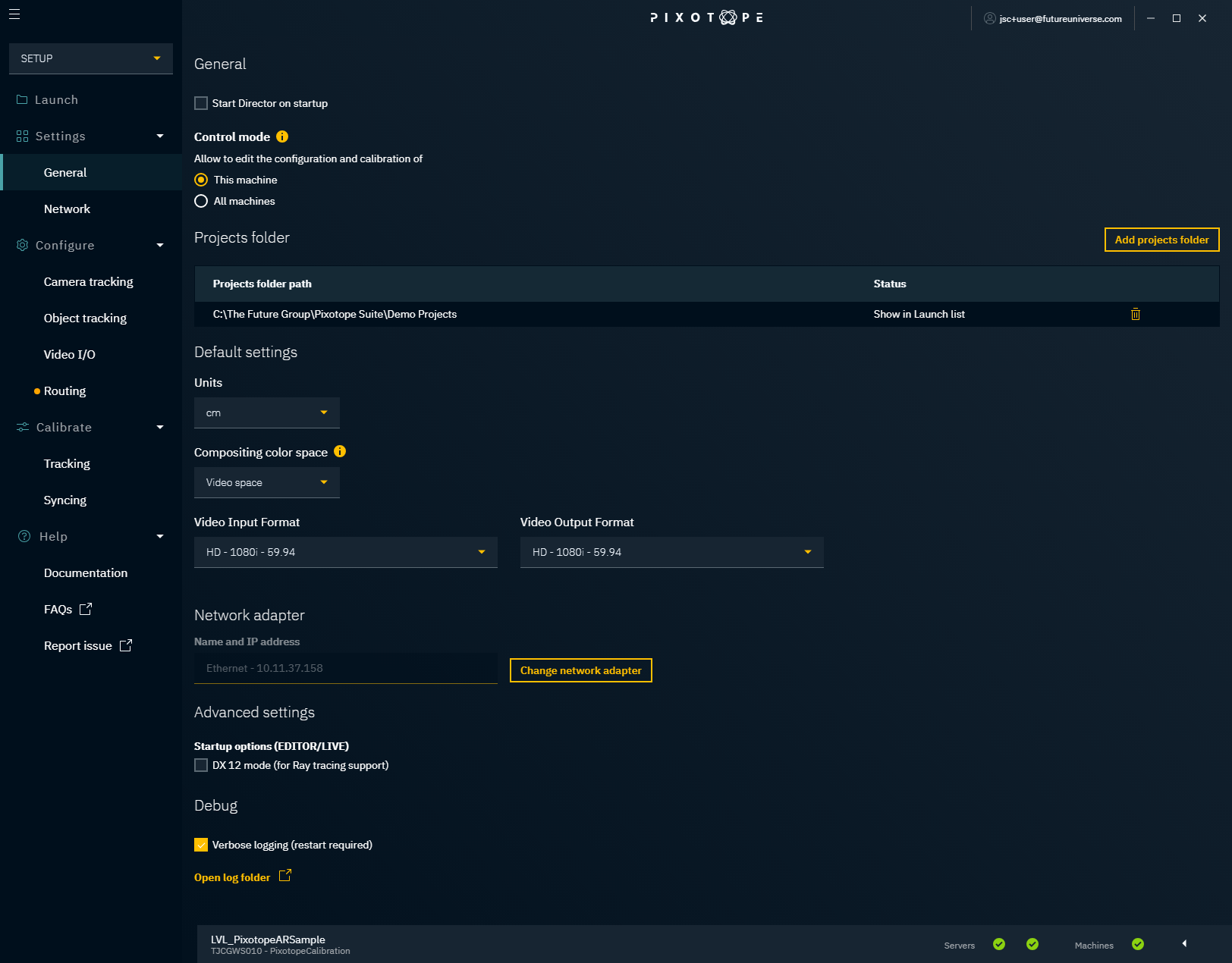
Start Director on startup
This option starts Director automatically when you start up your machine.
Control mode
The control mode determines whose configuration and calibration this Director is allowed to edit.
- This machine
- this Director is only allowed to change its own configuration and calibration
- use when setting up a single machine, or machines in parallel
- All machines
- this Director is allowed to change the configuration and calibration of all machines
- use when setting up multiple machines from one central machine
Learn more about parallel and central setup in multi-machine productions
Projects folder
This shows a list of projects folder paths on your local machine that are being "watched". All projects found are listed on the "Launch" page. This includes all projects in any subfolder. The demo projects folder path, chosen in the installation process, is listed by default.
Adding a project, level or control panel in one of the listed projects folder paths will automatically add them to the "Launch" page.
In multi-machine setups, the current projects folder must have the same local path on all machines.
Add projects folder
You can select a new projects folder path to be watched. All projects found in that folder or its subfolders will be added to the "Launch" page.
Adding a root folder such as C:\ is discouraged.
Remove a projects folder path
Clicking the trash can will remove that project's folder path. All projects within this parent path will be removed from the "Launch" page, unless there is an overlapping parent path.
To only watch projects in a sub folder (or to watch a specific project), you could add the subfolder (or the specific project) to the projects folder paths and then remove the parent folder from the list.
- Parent folder A - in projects folder path list
- Project folder 1
- Project folder 2
- Sub folder B - add to projects folder path list, then remove parent
- Project folder 3
- Project folder 4
Default settings
The default settings are used when creating a new project. The ones marked with an * can be overwritten on a per-project basis.
Default Units
Choose the preferred units for the Unreal Engine and the Tracking Server.
Default Compositing Color Space*
Choose the default compositing color space to be used in Configure → Video I/O.
Default Video Input and Output Format*
Choose the default video format to be used in Configure → Video I/O.
The frame rate of inputs and outputs must be the same!
Network adapter
Sets the network adapter to be used for communication between Pixotope machines.
Advanced settings
Startup options (Editor/LIVE)
DX 12 mode
This starts the Editor/Engine with the DX 12 flag. To fully enable ray tracing, ensure that:
- Windows 10 is running version 1809 or later
- DirectX 12 is installed
- the latest Nvidia RTX Graphic drivers are installed
- Ray Tracing is turned on in Pixotope Editor Project Settings → Rendering
Debug
If Verbose logging is enabled, Director logs more events than usual. This can help debug errors.
Network
The "Network" page gives you control over your network setup and allows you to check that all the servers (Data hub and Tracking Server) are now up and running.
For an overview, you can use the Status bar, which is present on all pages at the bottom of the Director.
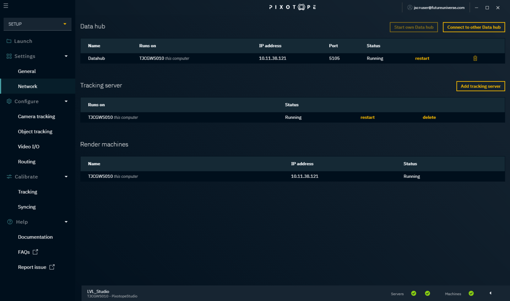
Data hub
The Data hub connects and handles all communication between the Pixotope machines of a virtual production. Each production needs just one Data hub.
Learn more about 1.5 | Single- and multi-machine setups.
Here you can:
- change who runs the Data hub
- restart the Data hub
- disconnect from a remote Data hub
- stop your local Data hub
Tracking Server
The Tracking Server receives and translates the camera and object tracking data and sends it on to the Pixotope Editor.
Here you can:
- add a Tracking Server
- 1 Tracking Server can be added/launched on each connected machine
- restart a Tracking Server
- delete a Tracking Server
Render machines
List of all machines connected to the same Data hub.
Configure
Under the "Configure" item on the main menu, there are several pages. These allow you to configure your Pixotope setup in accordance with your physical studio setup. This includes informing the system about your camera and camera tracking systems, object trackers, SDI video inputs and outputs, video and tracking routing.
Artist license
In an artist license there is no tracking server included. Configuration and calibration of camera systems are therefore not possible from within the Director.
This is how you can manually change the same settings in the Editor:
- Move the tracked camera
- Select the camera root in the world outliner
- Move the camera root
- Change camera settings
- Select the tracked camera in the world outliner
- Select the "CineCameraComponent" from the component list
- Find the settings under "Current Camera Settings"
Import Setup
All configuration settings are stored per project and on each Director machine individually. You can use "Import Setup from ..." to easily import setups from other projects or other machines.
To import a setup into the current project:
- Click "Import Setup from ..." in the "Launch" panel
- Select the machine you want to import a setup from
- Select the project
- Review the camera systems, media inputs and outputs and object tracker groups to import
- Camera systems, media inputs and outputs and object tracker groups with the same name will be overwritten
The "Final result" dialog shows whether any problems have occurred while importing or applying the setup. If there were, please check Configure → Routing and redo the routing.
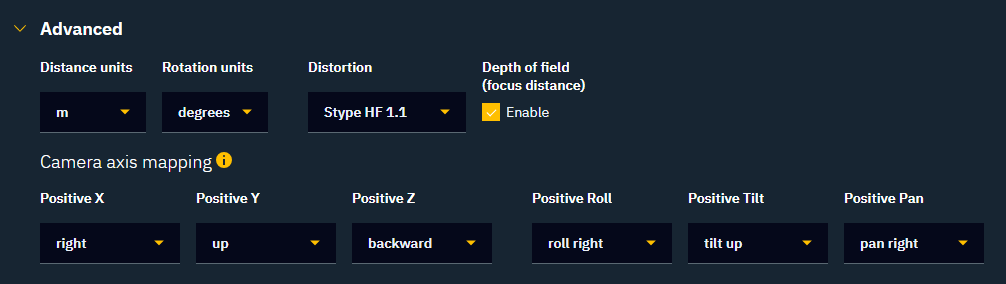
Camera tracking
Here you configure everything related to camera tracking.

Camera system
A camera system is a camera including its lens and a tracking system. The result is a tracked camera with various parameters tracked depending on the tracking system used.
- Click "Add camera system" and give it a descriptive name
- Choose a "Camera type" from the drop-down menu under "Camera and Lens"
- The default camera is 2/3 inch - 16:9. This covers all standard 2/3" broadcast cameras
- If you cannot find your camera type, click "Add camera type", choose a name and specify the filmback (sensor) width and height in mm
- Change the default lens aperture if needed
Choose the assigned tracking server

A tracking server can only be controlled from one Director. When choosing to control a tracking server from a second Director, all its previous settings will be overwritten.
Choose the camera tracking protocol your camera tracking system uses
Learn more about Setting up Camera tracking
Object tracking
Here you configure everything related to object tracking.
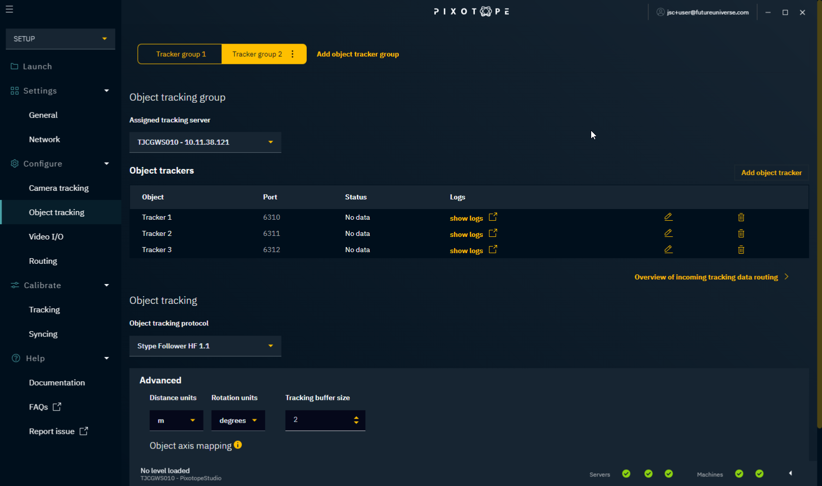
Object tracker group
An object tracker group is a parent for object trackers which share the same:
- tracking space
- tracking protocol
- tracking server
- Click "Add object tracker group"
- Give it a descriptive name
- Choose the assigned tracking server
-

A tracking server can only be controlled from one Director. When choosing to control a tracking server from a second Director, all its previous settings will be overwritten.
- Learn more about Tracking data routing
-
- Click "Add object tracker"
- Give it a descriptive name
- Change the port if needed
Object tracking
Object tracking protocol
Choose the object tracking protocol your object tracking system uses.
Advanced
The "Advanced" section covers protocol-specific details and how the data should be mapped. When you calibrate tracking, you might have to come back here if the object movement is mapped wrongly.
Learn more about 1.5 | Setting up object tracking
Video I/O
Here you define compositing color space and your video inputs and outputs.
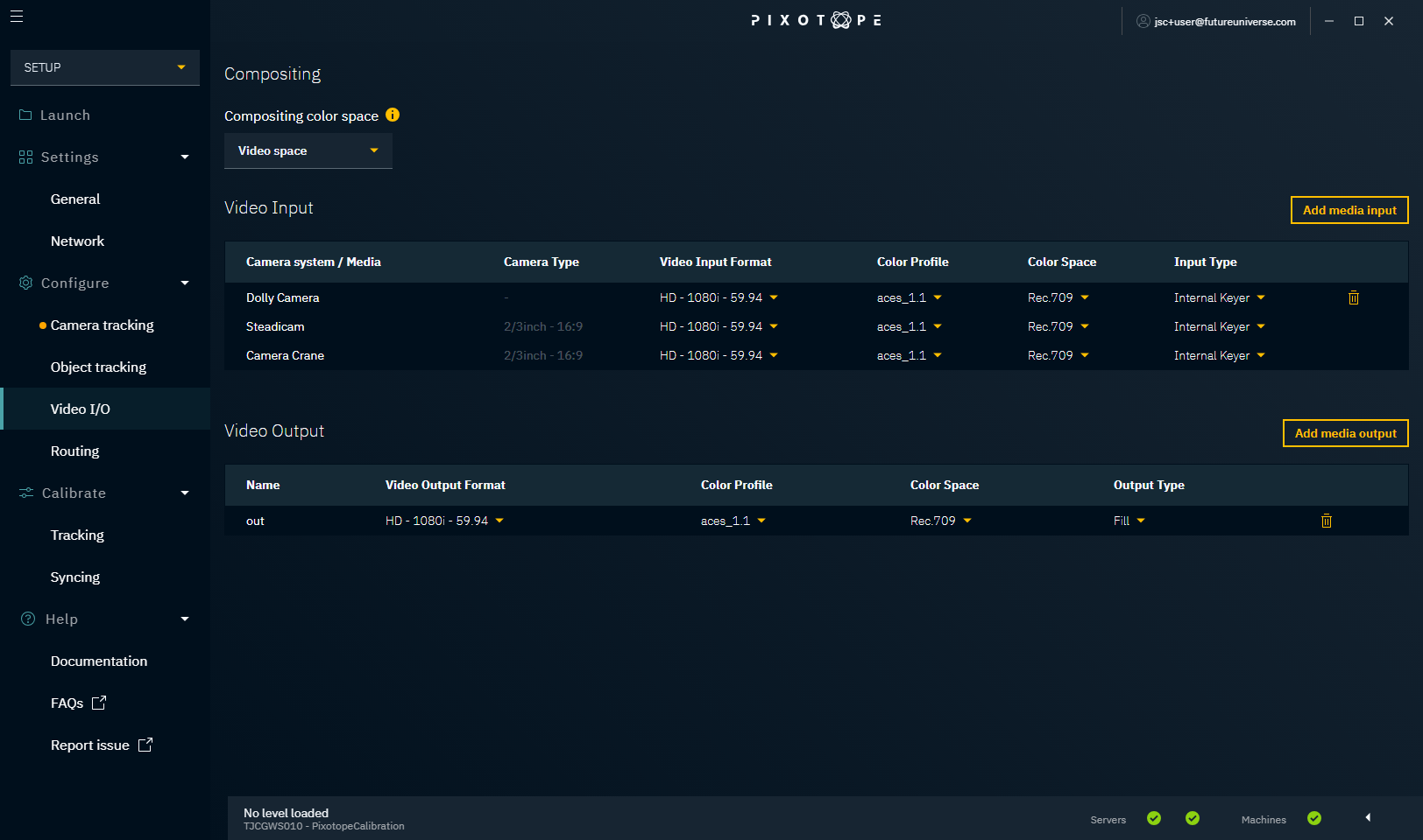
- Choose the project's compositing color space
- Add additional media inputs, if you need untracked video sources in your level
- All camera systems are listed by default
- Add one or more media outputs
- Optionally override the video input and output default settings
Learn more about 1.5 | Setting up video I/O
Routing
On the "Routing" page, we need to recreate the physical routing.
Camera, Media and Object routing
On this tab we set the input routing of
- Camera systems
- Object trackers
- Media inputs
and the output routing of
- Media outputs
Input routing
Under input routing:
- Set the genlock source for each machine
- There should be one common source for the genlock signal
- What is genlock?
A genlock is used to synchronize the camera and tracking data. For each machine, choose one of the following:
- External ref - genlock comes from an external ref signal
- External SDI x - genlock is used from a specified SDI input
- Internal - an internal genlock is generated
- Add all camera systems and media inputs physically routed to a specific machine
- Set the SDI Inputs they are wired to
- Add all object trackers whose tracking should be available on a specific machine
Only one camera system can be added per machine.
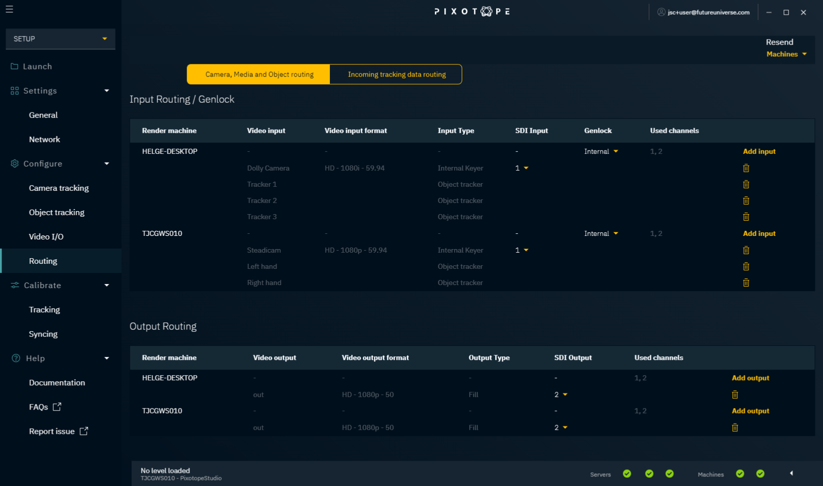
Output routing
Under output routing:
- Add all outputs planned for a specific machine
- Set the SDI Output they are wired to
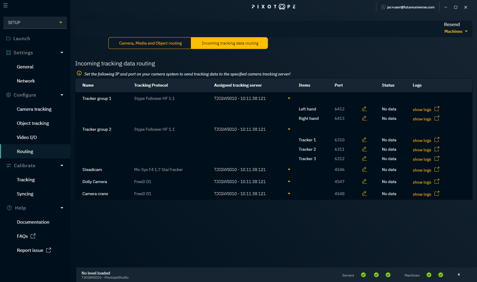
Incoming tracking data routing
The initial incoming tracking data routing is done on the individual camera systems and object tracker groups. On this tab you:
- get a routing overview of all incoming tracking data
- can edit the routing
- Choose which Tracking Server should be assigned to which camera system and object tracker group
- Best practice for:
- camera systems: Run a separate Tracking Server for every camera system on the machine the camera system will be routed to
- object tracker groups: Use the Tracking Server on the machine most of the object trackers will be routed to
- Best practice for:
- Change the port if needed
- On your camera and object tracking system, enter the IP address and port number of the assigned Tracking Server
- This is where your tracking data should be sent to
- For the Ncam system, the IP address and port number should be entered in the Advanced section of the camera tracking protocol
- Check the status field
- Your tracking configuration is set up correctly if it shows incoming data
- You can also check the 1.5 | Network status in the Editor
Calibrate
Under the "Calibrate" item in the main menu, there are 2 pages: "Tracking" and "Syncing".
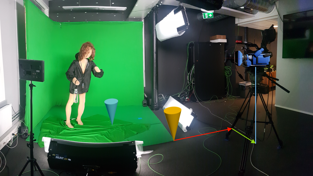
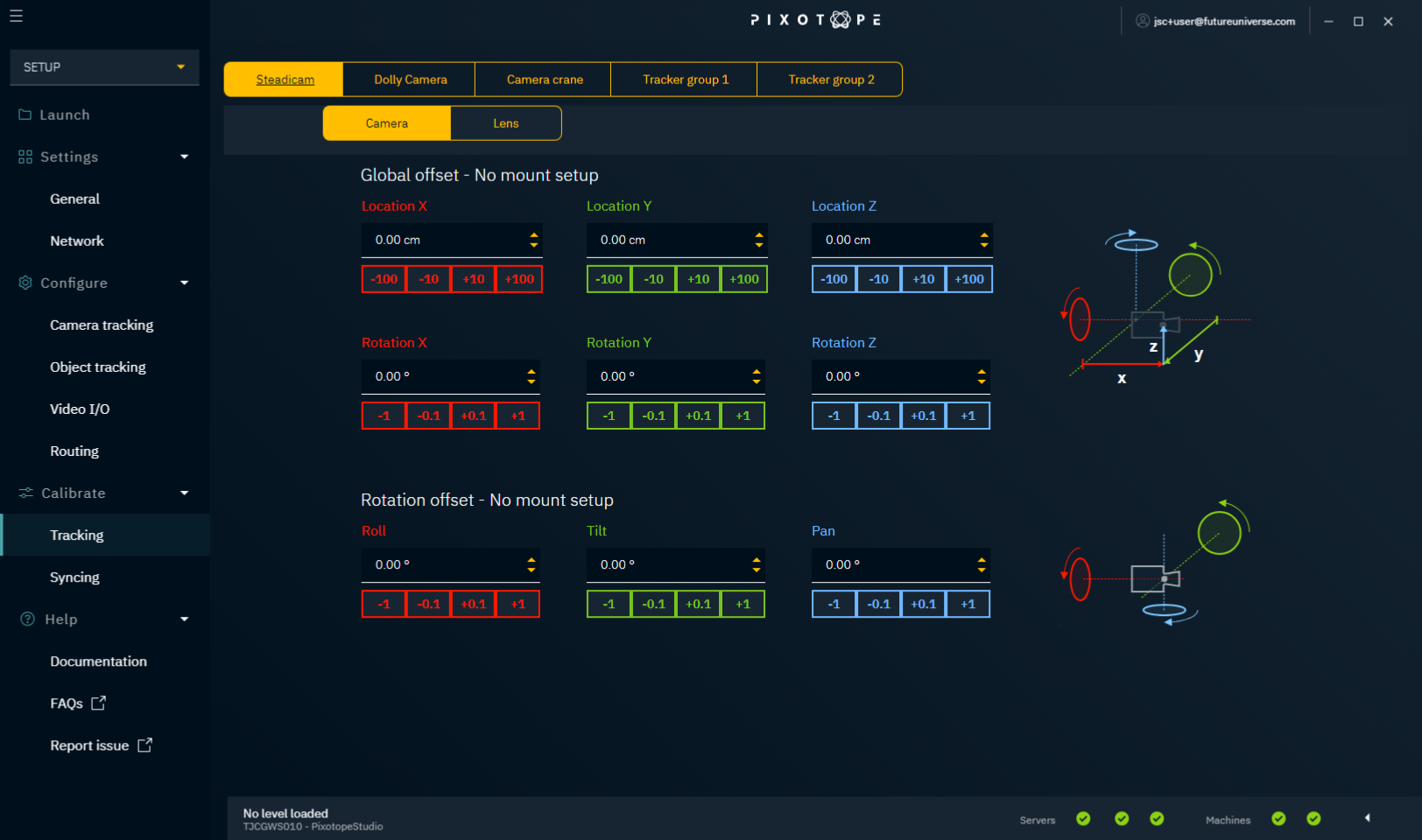
Tracking
The tracking system is calibrated so it sends position and rotation data of the physical camera or object relative to the studio origin* into the Editor.
Physical camera → "TrackedCamera" in the Editor
Studio origin → "CameraRoot" in the Editor (yellow cone)
* The studio origin is a defined and marked point in your studio. It is practical to make that a point visible to the camera.
For advanced tracking systems
Advanced tracking systems will already give you position and rotation relative to a defined studio origin. For these systems, we suggest doing the tracking calibration on their end.
If you need technical support in calibrating the tracking system, please contact the vendor of your camera tracking system.
For simple tracking systems
Simple tracking systems provide only parts of the data, for example only rotation data. In this case, use the tracking panel to manually offset the tracking data so that you end up getting position and rotation data relative to the studio origin. This data offset is applied in the Tracking Server.
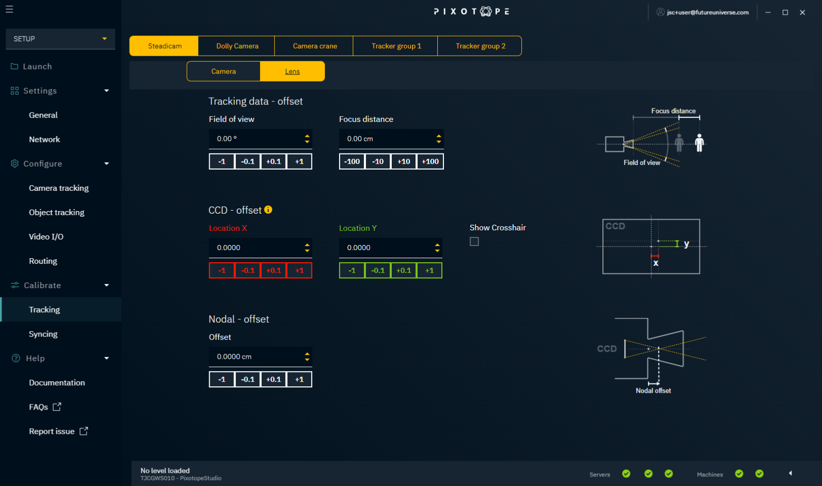
Camera
Depending on the selected camera mount, different offset options are provided:
Lens
Check camera tracking
- Define and mark your studio origin
- In the Editor: check that "CameraRoot" is 0,0,0
- In the Editor: place a calibration cone at the CameraRoot
- The marked point on stage and the calibration cone should match up
- Move the camera to the outer sides of the field of view and see whether the marked point and calibration cone still match up (disregard time slipping)
Syncing
Depending on the video pipeline, you can end up with delayed video or tracking data. To avoid 3D images slipping when the camera or object is moved, we need to synchronize video data and tracking data.
Check syncing
- Pan the physical camera quickly and stop abruptly
- Check to see whether the calibration cone slips temporarily from the marked point
- If the graphic moves first:
- Subtract video input delay
- If that is not possible, then add tracking delay
- If the camera feed moves first:
- Subtract tracking delay
- If that is not possible, then add video input delay
- If the graphic moves first:
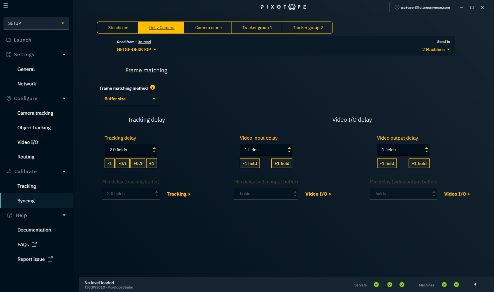
Frame matching methods
Buffer size (no frame matching)
This ensures a stable buffer size by deleting overflow, and by duplicating packets when the buffer size is too low.
- Requires manual syncing
- Will cause stuttering when tracking data is unstable
Timecode (experimental)
This method uses timecode to auto lock video and tracking data.
Learn more about 1.5 | Setting up timecode (LTC)
Tracking data with embedded timecode is currently supported by the following tracking systems:
- Ncam
- SMT
Trackmen
Stype Red Spy
This feature is in Experimental stage and can be accessed via command line.
Enable Timecode frame matching method
Add the following lines to
UPROJECT_DIR/Config/DefaultEngine.ini[SystemSettings] TTMTextureHandler.LtcSourceNumeric = 0 FrameMatcher.Method = 2TEXT- Restart the Pixotope Engine
Variables
- Video timecode source*:
TTMTextureHandler.LtcSourceNumeric→ See 1.5 | Useful console commands Frame matching method:
FrameMatcher.MethodMethod value Buffer size 0 Timecode 2 Ideal time 3 Tracking delay offset:
FrameMatcher.TimecodeDelayOffsetThis delay offset (default = -2) modifies the value shown in the Calibrate → Syncing Panel
e.g. a Tracking delay offset of -2 and a Tracking delay of 3 results in an actual delay of 1
The offset is only relevant when using Timecode frame matching.
Set variables via command line
All variables are available as console commands from within the Engine. The variable marked with * needs a restart of the video pipeline (e.g. can be achieved via the Routing panel by changing an input spigot back and forth).
Reset to Buffer size frame matching method
- Remove the added lines or set
FrameMatcher.Method = 0 - Restart the Pixotope Engine
Tracking delay
This setting allows you to add a delay to the tracking data.
Video input delay
This setting allows you to add a delay to the video input.
Video output delay
This setting allows you to add a delay to the video output.
Creating your first project
Continue to 1.5 | Setting up a Pixotope project.